Quantcast
Channel: Embedded Community : All Content - All Communities
Viewing all 3032 articles
Browse latest View live

IBM World of Watson 2016 Las Vegas, NV OCT 24th - 27th

$
0
0

World of Watson will show you the technologies and strategies that will help propel your company into the future. Here’s how:


EXPERIENCE

Innovation you can touch

Where else will you will see a cognitive dress, use your own cognitive concierge or kick the tires of a Watson self-driving car? Get inspired by case studies and groundbreaking research, then see what Watson can do for your business and its customers.


DATA & ANALYTICS

Get next-level insight

World of Watson incorporates the kind of information you gained from IBM Insight — the tools to get the best out of your data — and raises the game. You’ll see how Watson’s capabilities give you an unprecedentedly broad view of your business, its competitive landscape and what it takes to make your customers act.


KEYNOTES

World’s top thinkers

Engage with an elite group of thought leaders, top academics, inspired architects, data scientists, developers, engineers, inventors and business leaders.


NETWORKING

Broaden your mind

Meet with 20,000 fellow enthusiasts and experts to discuss the hottest trends at a mind-blowing array of sessions, receptions, luncheons and celebrations.


FUN

Downtime is creative too

Give the learning a chance to sink in. Enjoy Grammy award-winning rockers and Las Vegas hometown heroes Imagine Dragons perform exclusively for World of Watson attendees.


Register Here


Radisys_Intel_Rack-Scale_SDN_NFV_(2016oct_whitepaper).pdf

How to configure the Intel EMGD on Linux OS using CED lite ?

$
0
0

Hi,


I work with ISP on Fedora 18, at first I use Timesys Fedora 18 Gold and MR1.  Because of new ISP driver I want to make Fedora MR2 to use new driver and start camera, but i have problem with configuration ... I try a lot of thing  and I trying more than 4 weeks but I don't know how to  do it ?  I guided with Linux guide for EMGD  and  user guide for make Fedora MR2, but I don't have any good result, I don't know maybe I doing something wrong. Problems starts when I installed xorg-server-1.14.5  and copy xorg.conf file in folder /etc/X11/  ... after that I start command as root user /usr/bin/startx ... fedora look like restarted and and when this action finish I can't move with mouse and nothing with mouse .


Could somebody told me what I do wrong?


P.S  xorg.txt  I create with CED-Lite


BR,

Teja

Build Smart Signage: 4K OPS Module with Remote Management Feature- OPS500-501

$
0
0

The Axiomtek OPS500-501 is a 4K resolution OPS compliant digital signage player supporting Intel® Active Management Technology (AMT) 11.0 for better remote management. The space-saving OPS signage module is powered by the 6th generation Intel® Core™ processor (formally codename: Skylake) with Intel® Q170 chipset. It has one 260-pin DDR4-2133 SO-DIMM socket with up to 16GB memory capacity. Compliant with the Intel® OPS architecture, the 4K-ready signage player provides a high level of compatibility as well as simplified installation, maintenance and deployment for a lower total cost of ownership. The smart cableless OPS500-501 is ideal for multi-display applications in education, corporate, airport, shopping mall, hospitality, religious organization, bank, retail store, restaurant, performing art center, and many more.


The Axiomtek OPS500-501 has 4K Ultra High Definition (UHD) at 60Hz content, dual displays, and real-time audio and video to provide excellent multimedia performance. Featuring LGA1151 socket-type CPUs, the signage system can be maintained and upgraded easily.  Moreover, by supporting Intel® AMT 11.0, the high-performance Intel® Skylake OPS signage module can be managed, monitored, diagnosed and repaired remotely. Operator can work more efficiently while saving time and costs.


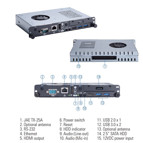
The outstanding digital signage player, the OPS500-501, is connected to OPS-compliant display via a standardized JAE TX-25A plug connector that supports DisplayPort, HDMI 2.0, UART, audio, USB 3.0 and USB 2.0 signals. To meet various application needs, the powerful digital signage system offers rich I/O interfaces on its front panel, including one USB 2.0 ports, two USB 3.0 ports, one COM port, audio (in/out), HDMI and a Gigabit Ethernet port. This space-saving OPS signage player has one PCI Express Mini Card slot for WLAN connectivity and features one 2.5” SATA HDD for extensive storage needs.


For more digital signage product information or pricing, please visit our global website at www.axiomtek.com or contact one of our sales representatives at info@axiomtek.com.tw.


Advanced Features:

  • Intel® Open Pluggable Specification (OPS compliance)
  • 6th generation Intel® Core™ i7/i5/i3 & Celeron® processor (Skylake)
  • Supports DDR4-2133 SO-DIMM max. up to 16GB
  • Supports 1 PCI Express Mini Card slot
  • Supports 4K@60Hz resolution
  • Easy installation and maintenance
  • HDMI for 2nd Ultra HD display
  • Intel® AMT (Active Management Technology) 11.0

OPS500-501 OPS Digital Signage Player

Case Study: Avoiding Bottlenecks, Snail Threads, and Pitfalls in RADAR Software

$
0
0

CS-tn-Avoiding-Bottlenecks-Snail-Threads-and-Pitfalls-in-RADAR-SW.GIF

Facing the specter of parts obsolescence, antiquated computer architecture, and closed proprietary systems, the customer wanted a technology refresh that would facilitate the possible retrofit of several existing radar systems. For both the upgraded systems and new designs going forward, the customer desired open, portable technologies that would improve performance, increase reuse, and lower costs. They believed that by leveraging the development infrastructure, technology roadmap and investments of standardized Commercial Off the Shelf (COTS) vendors, they could achieve their hardware and software objectives.


The challenge was to design an Application Ready Processor (ARP) consisting of processing hardware, operating system, and processor middleware for a podclass radar system using available off-the-shelf hardware. The ARP was required to demonstrate performance against a set of Synthetic Aperture Radar (SAR) and Ground Moving Target Indicator (GMTI) benchmarks, while meeting specified size, weight and power (SWaP) constraints. In addition to characterizing the currently available hardware, the customer wanted to quantify expected near term processing gains from the next generation of hardware. As part of the solution, the benchmarks could be optimized to improve performance, but the accuracy of the improvements must pass verification.


Visit the Curtiss-Wright website todownload the case study and  learn more about how the Intel Core i7 processing solution and OpenHPEC tool suite solved this challenge.

Intel® Quark™ SE Microcontroller: Enabling Decision-making at the Edge

$
0
0

One of the biggest challenges with deploying intelligence at the edge is keeping power consumption in check. Making smart decisions can take a lot of processing, which can burn a lot of power.


The Intel® Quark™ SE microcontroller C1000 tackles this dilemma with an innovative pattern-matching engine and a smart sensor subsystem. Figure 1 shows a diagram of the processor with the pattern-matching engine and sensor subsystem highlighted in orange.


Figure 1. The Intel® Quark™ SE microcontroller includes a pattern-matching engine and sensor subsystem.


With its new pattern-matching engine, the Intel Quark SE microcontroller can perform simple pattern detection on sensor data without engaging the main processor core. Inputs like vibration, temperature, or current can be passed directly from the sensor subsystem to the pattern-matching engine. If the engine finds a pattern it has been looking for, it can trigger a wakeup event to the main processor. The processor can then take whatever action is needed—such as starting up a piece of equipment or sending a message to maintenance staff.


The sensor subsystem also can operate independently of the main core. The heart of this system is a 32-bit ARC EM DSP core that can offload sensor processing from the main core. This allows the main core to stay in sleep mode until the sensor processing is complete.

The DSP core has hardware support for operations like multiply-accumulate, fractional arithmetic, floating point, divide, square root, and trigonometric functions. These arithmetic capabilities enable the core to perform initial signal processing and signal-conditioning functions like sensor fusion, data averaging, filtering, artifact rejection, and error correction.


Inside the Pattern-Matching Engine

While the sensor subsystem will be familiar to anyone who has programmed a DSP, the pattern-matching engine is more novel. The pattern-matching engine features 128 neurons that can perform two types of pattern recognition: K-nearest neighbor (KNN), where the input consists of the K-closest training examples, and radial basis function (RBF), which depends on the distance from the origin to correctly classify new instances.


Upon processing a pattern, the engine returns one of three states: identification, uncertain, or unknown. Up to 32,768 identification categories can be programmed.


When it comes to programming, neurons can have three states in the chain: IDLE, Ready To Learn (RTL), or Committed (see Figure 2). It becomes Committed as soon as it learns a pattern. A control line then changes its status from Ready To Learn to Committed. The next neuron in the chain then becomes the Ready To Learn neuron. The contents of Committed neurons, a representation of the knowledge they have built autonomously via learning examples, can be saved and restored.

Figure 2. Neurons exist in one of three states. (Source: General Vision)


Neurons are trained by example and decide autonomously when it is necessary to commit new neurons and/or correct existing ones. In the course of learning, only novelty—new information—results in a new committed neuron.


When a new example is presented for learning, the neural network first attempts to recognize it. If the example is recognized by one or more neurons, and they all agree on its category, the new example is discarded since it does not add any new information to the existing knowledge base. If the example is not recognized by any existing neurons, a new neuron is automatically added to the network to store the new example and its value.


Edge Intelligence in Action

One company taking advantages of these capabilities is Dublin-based Firmwave, which uses the processor in its Edge 3.0 wireless sensor platform (Figure 3). The Firmwave* Edge supports Zigbee*, Thread, RFID, NFC, Wi-Fi, Bluetooth*, LoRa*, SIGFOX*, and cellular connectivity. It comes with a host of on-board sensors, including temperature, humidity, light, pressure, position, and acceleration as well as a 36-pin expansion connector providing flexibility and extensibility.


Figure 3. Firmwave’s Edge wireless sensor platform is optimized for low power.


Adrian Burns, CTO and co-founder at Firmwave, notes that his company’s interest in Intel Quark SE microcontroller is in leveraging its on-board sensor subsystem to do data classification on the fly, offloading tasks from the core and enabling the processor to stay in low-power mode longer. He says, “We wake up the processor only when we want to do data connectivity to the cloud or gateway, allowing Firmwave Edge customers to reduce energy use.”


Burns notes that many of the company’s engineering efforts are centered on power optimization. When they see an opportunity to reduce power consumption, as the Intel Quark SE microcontroller does, “we have to be all over it,” he says.


A Smarter Way to Do Intelligence at the Edge

The Intel Quark SE microcontroller is in many ways a remarkable departure from Intel’s traditional approach. Adding the pattern-matching engine and DSP core in the sensor subsystem offload a considerable amount of processing from the main core, where Intel would traditionally focus its efforts. But it is clear that this new approach has resulted in high intelligence at low power. It will be interesting to see how the new capabilities will be deployed in the field.


Learn More

Contact feature member:


Solutions in this blog:


Related topics:

Firmwave is a General member of the Intel® Internet of Things Solutions Alliance.


Murray Slovick

Roving Reporter (Intel® Contractor), Intel® Internet of Things Solutions Alliance
Simplify Sensor Connections with Modular IoT Software

$
0
0

One of the big challenges with IoT design is integrating all of the sensors. A typical IoT deployment has multiple sensors—such as temperature, humidity, and motion sensing—as well as multiple communication protocols—including Wi-Fi*, ZigBee*, and Bluetooth* low energy, to name a few. Sorting out all the firmware for the various sensors and networks can be a time-consuming and tedious process.

American Megatrends, Inc. (AMI) is attacking this problem with tools that abstract the sensor interfaces. By providing a modular, plug-and-play approach, AMI says it can significantly speed up the early stages of the development cycle.


Modular Firmware

The foundation of the approach is the AMI RTOS* and its accompanying integrated development environment (IDE), shown in Figure 1.  The IDE centers around schematics that show how sensor interfaces tie to pins of the system’s embedded controller. Developers need only select their preferred RF modules and sensors, and the dev environment will automatically produce customized firmware.


Figure 1. The AMI RTOS* is accompanied by an integrated development environment (IDE).


Because developers no longer need to learn the details of each interface, development time can be reduced significantly. In addition, this plug-and-play functionality makes it easier to swap components when design requirements change.


Sensor Hubs

The RTOS provides additional functionality needed to construct a sensor hub, such as a web-accessible device management user interface. Indeed, the RTOS is just one element in AMI’s larger offerings for IoT designs. As shown in Figure 2, AMI offers solutions that extend from the sensor hob to the IoT gateway and even into the cloud.


Figure 2. AMI's scalable IoT solution architecture.


IoT Gateways

Devices running the RTOS can communicate with a gateway that runs AMI LINUX*. The OS is designed to enable efficient administration. For example, to add a new gateway or sensor array to the network, you scan a QR code into an app on a mobile device.


The gateway OS has multiple fail-safe mechanisms. If replacing hardware is necessary, getting operational again is straightforward with restoration of previous configurations, whether through a factory image restore option, image reinstall with a USB key, or directly from the cloud.


Efficient Edge Processing

Although AMI’s solutions can be used with any Intel® processor, the company sees particular advantages to using Intel® Quark™ processors. These processors have low energy needs as you would expect in embedded and IoT applications, and yet provide more performance per watt than other chips. That translates into important advantages in operations.


If sensor data needs significant filtering, an Intel Quark processor can handle that workload—along with some heuristics—at the sensor hub. Pushing this processing all the way out to the sensor hub frees the gateway up for other tasks. Hub-level filtering also reduces unnecessary data transmission, allowing gateways to communicate with more sensors than would otherwise be possible.


Cloud Connectivity

AMI LINUX provides connectivity to such popular cloud options as Amazon AWS*, Microsoft Azure*, and IBM Bluemix* to complete the data path. Developers can also use AMI CLOUD SERVICES, a private cloud service designed by AMI for IoT management and use.


AMI CLOUD offers significant administrative and operational advantages, like fail-safe backup for all sensor hubs and gateways. AMI CLOUD additionally protects uptime with a many-to-many rule engine that manages sensor rollover in case of a negative event. Robust data analytics close the loop so companies can make use of the collected sensor data and make results available for further data analysis and decision support.


Take the Pain out of IoT

In short, AMI’s software stack takes much of the pain out of IoT sensor integration—and it provides a convenient path to the cloud. To see other firmware and OS solutions from members of the Intel® Internet of Things Solutions Alliance, visit the Solutions Directory.


Learn More

Contact featured member:


Solutions in this blog:


Related topics:


American Megatrends, Inc. is an Affiliate member of the Intel® IoT Solutions Alliance.


Kenton Williston

Roving Reporter (Intel Contractor), Intel® Internet of Things Solutions Alliance


New Technologies Extend Wireless Sensing Range

$
0
0

As more sensor nodes connect over wireless networks, there is a growing need for alternatives to interfaces like Wi-Fi*, Bluetooth*, and ZigBee*. Many Internet of Things (IoT) applications require lower cost and power consumption, longer range, and an improvement in the number of devices per router or aggregation point.


LoRa and LTE Cat. 1 are emerging as two leading alternatives. While these are proving successful as interfaces, there are still questions about interoperability, security, and manageability—and these are being addressed through gateways based on the Intel® IoT Platform.


LoRa connects many devices over long ranges

LoRa (short for Long Range) is a low-power specification designed for battery-operated devices (Figure 1). A typical interface can handle about 65,500 end devices with a range of up to 50 km and data rates up to 50 Kbit/s. Combined with localization capability, it is easy to see why LoRa is so attractive for long-range, low-power IoT sensing applications.


Figure 1. The LoRaWAN MAC sits on top of the LoRa PHY layer.


On top of the LoRA physical layer (PHY) sits the LoRaWAN media access control (MAC), which controls both the PHY layer and access to the backhaul network. LoRaWAN uses an adaptive data rate (ADR) mechanism and star-of-stars topology to ensure scalability as the number of nodes increases.


A LoRa gateway may need to aggregate data from other networks, including Bluetooth and Wi-Fi, and perform data conditioning and other number-crunching. Thus, a LoRa gateway may need high performance in addition to the aforementioned security, scalability, and manageability.


A good example is the SGWMC-X86LR-12132 Gateway from EXPEMB (Figure 2). It is designed for scalability and to support multiple interfaces and software services. In addition to LoRa, this gateway supports a 1-Gbit Ethernet link, Wi-Fi, 3G/4G, and Bluetooth, simultaneously. This gateway’s support of multiple wireless interfaces is critical as not all radio protocols support IP natively, so the gateway functions as both an aggregator and IP translator.


Figure 2. The Embedded Experts gateway supports multiple interfaces.


To enable this rich functionality, the gateway is built on the Intel® Atom™ processor E3800 product family. With up to 4 speedy cores, the Intel® Atom™ processor has plenty of performance for aggregation and translation. This performance also supports the gateway’s software services, including remote firmware updates and multiple layers of security, such as TLS and IPSec.


While LoRA is the newest of the long-range IoT connectivity specifications, cellular network providers are working hard to lower power and cost to provide IoT connections over licensed bands. This is important because LoRa uses unlicensed bands. In theory, using licensed bands reduces interference and makes for more reliable connections, with higher data rates.


The LE910 series of modules from Telit support one such interface: LTE Cat. 1 (Figure 3). The module supports the category’s full 10-Mbit/s downlink and 5-Mbit/s uplink speeds and is optimized for both Verizon and AT&T.


Figure 3. The Telit LE910 LTE Category 1 module supports rates of 10 Mbit/s for the downlink at 5 Mbit/s in the uplink.


The module comes with IP support, as well as UDP/IP stacks and HTTP, SMTP, FTP, and SSL. It also supports a host of services such as module management that make IoT deployments under mobile networks more effective. Other features include multi-constellation (GPS + GLONASS) positioning, over-the-air firmware updates, and MIMO and receiver diversity support.


The module can be used in gateways like Quanmax UbiQ-100 Series (Figure 4). In addition to the built-in features like an Intel® Atom™ processor, HDMI, USB 3.0, USB 2.0, and COM ports, Quanmax offers integration services to incorporate custom features like LTE modules.


Figure 4. The Quanmax UbiQ-100 Series can incorporate any RF module.


The Quanmax gateway is also notable for its software options. Preloaded options include security management; remote monitoring management; wireless monitoring; data collection & translation; and more.


Wireless options for billions of nodes

As the IoT grows to billions of nodes—including countless wireless sensors—it is becoming more important than ever to make sure the right networks are applied to each application. LoRa and LTE Cat.1 are just two of the leading options for wireless sensors. To see more ideas for wireless connectivity, check out the Solutions Directory listings for wireless access and IoT gateways.


Learn More

Contact feature member:

Solutions in this blog:


Related topics:

Telit is an Associate member of the Intel® IoT Solutions Alliance. EXPEMB and Quanmax are General members.


Patrick Mannion

Roving Reporter (Intel Contractor), Intel® Internet of Things Solutions Alliance


Keep an Eye on Production with This Smart Factory Solution

$
0
0

By Craig Szydlowski


To keep a factory operating smoothly, manufacturers need to keep a close watch over production status, equipment conditions, and operator activities. It’s a big challenge to collect all of the necessary data, and making sense of the numbers can be a real headache. What if a smart system could do all this automatically—and what if it could predict the future?


ADLINK recently demonstrated an end-to-end smart factory system that does just that. Its system combines machine sensors and controllers, smart cameras, IoT connectivity, and cloud-based business intelligence (Figure 1). By bringing these elements together, the system not only can monitor a production line in real time but also predict order fulfillment and maintenance needs.


Figure 1. The ADLINK demo includes an intuitive interface.


Predictive Quality and Maintenance

The heart of the system is the ADLINK PMQi, which intelligently automates production line quality and maintenance. This end-to-end data analytics platform was developed in collaboration with Intel and IBM, and uses Intel’s high-performance and highly secure hardware along with IBM’s Predictive Maintenance Quality (PMQ) Business Analytics platform.


The platform provides advanced analytics from the edge to the cloud. At the edge, the PMQi Cognitive Gateway runs a scoring engine to predict production line behavior and take corrective actions as needed. In the cloud, the IBM PMQ platform performs advanced analytics to reduce failure rates and predict maintenance needs.


ADLINK recently showcased a demo showing how these capabilities can also predict order fulfillment. When production is activated by an order, the system calculates an estimated time to completion and sends it to the business center in the cloud. If the production line is impacted by an event, like a change in conveyor speed, the system recalculates and reports the new completion time. If an operator hits the emergency stop button, the system halts production and informs the operations center.


A Fully Connected Factory

To monitor machine conditions and production status, the demo uses an ADLINK USB-2405 data acquisition (DAQ) unit to collect data from temperature, DC power voltage, and conveyor tension sensors. If a sensor measurement (e.g., temperature reading) exceeds a set limit, an alarm is sent to the operations center, the LED tower is triggered, and the production line is shut down. Operators can change system settings, such as the maximum operating temperature, via a configuration panel.


The demo also uses an ADLINK NEON-1040 smart camera to evaluate product quality. As products move on the conveyor, the camera performs optical character recognition (OCR) on the product labels. It captures high-resolution images, reports pass/fail status, and calculates the yield rate.


Data from the sensors and the camera are passed over to the ADLINK MXE-200i gateway, which in turn routes the data to the cloud. The gateway is based on Intel® IoT Gateway Technology, which provides a robust platform for secure, reliable connected designs. To this foundation ADLINK has added APIs that enable easy connection to cloud infrastructure such as IBM Bluemix*, Microsoft Azure*, and Amazon Web Service* (AWS).


Machine Vision

Machine vision requires high image resolution and rapid frame rates. Excelling in both these areas, the ADLINK NEON-1040 (Figure 2) features 4-megapixel image capture at 60 frames per second (fps). The camera has a minimal footprint and a rugged IP67-rated construction to withstand harsh industrial environments. Its quad-core Intel® Atom™ processor E3845 provides high-performance computing, and FPGA coprocessors and GPU deliver advanced image processing beyond the capabilities of conventional smart cameras.


Figure 2. The ADLINK NEON-1040 offers excellent performance.


The Intel® processor also makes it possible to connect a second camera to the NEON-1040 to capture images from other angles, further extending vision capabilities. Because it is based on an Intel® Atom™ processor, the camera offers flexible software development support, including GeniCAM*, GenTL* support for image acquisition, and OpenCV* and OpenCL* programming. With optional Microsoft* Embedded Standard 7, support for 64-bit instructions, onboard 2 GB RAM, and up to 32 GB storage, the NEON-1040 provides a stable, high-performance software operating environment for high-speed machine vision applications.


Complete Smart Factory Solution

Real-time production performance management, made easier by the IoT, can increase overall factory productivity. It is also possible to collect and analyze data to implement machine defect management and equipment failure analysis with the end goal of improving overall product quality and operations efficiency. This can be done using an ADLINK-based system that integrates machine vision, motion control, and the cloud with the help of Intel processors and IoT technologies. To see other industrial automation solutions from members of the Intel® Internet of Things Solutions Alliance, visit the Solutions Directory.


See the system in action.


Learn More

Contact feature member:

Solutions in this blog:Related topics:

ADLINK is a Premier member of the Intel® Internet of Things Solutions Alliance


Craig Szydlowski

Roving Reporter (Intel Contractor),Intel® Internet of Things Solutions Alliance

Atom Processor E3825 BIOS POST Codes?

$
0
0

Hi~


I'm developing test board with E3825.

7-segments are connected to test board for POST status display.

7-segments are displaying "0000" or "000C" and board has been stopped.

So, I want to know the meanings of "000C" or any other displays.

Somebody can help me to find the document about the meaning of POST Codes?

What is the correct FSP to C222 PCH chipset

$
0
0

Hi everyone


I'm starting my studies on Intel firmware support package.

Currently I'm trying to generate a bios image to deploy on a system, and the system I have has a C222 PCH chipset.

The system I'm using for this studies is this one:  https://firmware.intel.com/develop/server-development-kit


My question is. Where can I find the correct version of FSP to be used for this?


At GitHub - IntelFsp/FSP: Repository of FSP binaries posted by Intel  I was not able to be sure about the FSP package to be used.


Could someone please help me?


The idea is to study FSP and coreboot to create a bios for this system. Just for fun


Thanks and Regards

如何运用flashall对Edison进行刷机?

$
0
0

在三种不同系统:WindowsLinuxMac下运用flashall script 脚本进行操作,具体参考链接https://communities.intel.com/docs/DOC-25154


---------------------------------------------------------------------------------------------------------------------------

更多智能系统的技术交流,请关注我们微博weibo.com/onlinesalesgroup、并浏览我们官方社区

http://embedded.communities.intel.com/community/zh_cn,或者官方技术交流QQ群120966104。

------------------------------------------------------------------------------------------------------------------------------


如何查看edison的image具体版本信息?

$
0
0

运用 cat /etc/version指令就可以看到当前版本信息


---------------------------------------------------------------------------------------------------------------------------

更多智能系统的技术交流,请关注我们微博weibo.com/onlinesalesgroup、并浏览我们官方社区

http://embedded.communities.intel.com/community/zh_cn,或者官方技术交流QQ群120966104。

------------------------------------------------------------------------------------------------------------------------------

如何在Edison中建立VPN连接?

$
0
0

可以利用l2tp package 实现,具体参考链接https://communities.intel.com/message/322501#32250


---------------------------------------------------------------------------------------------------------------------------

更多智能系统的技术交流,请关注我们微博weibo.com/onlinesalesgroup、并浏览我们官方社区

http://embedded.communities.intel.com/community/zh_cn,或者官方技术交流QQ群120966104。

------------------------------------------------------------------------------------------------------------------------------

PLTRST signal never deasserts on boot

$
0
0

I'm using the X-Powers PMIC and the Cherry Trail T3 package. On power up, all the core processor rails come up correctly; CORE_PWROK and VCCA_PWROK both go high; but the Cherry Trail never deasserts PLTRST#. This is preventing the system from fully booting. I haven't been able to find shorts in the board that might be causing the problem, and I've been through several reference designs and I think I'm matching them as closely as I can, but I still haven't been able to figure out what's wrong. To me it looks like the PMIC is working but something is going wrong on the Atom side. The datasheet states that PLTRST# should desassert when CORE_PWROK is stable and PMC_RSMRST is deasserted; when I scope CORE_PWROK it looks stable for 500ms before the PMIC resets, and PMC_RSTRST is deasserted stably. Is there another requirement for PLTRST# deasserting that I'm missing?


如何改变Edison breakout 板上的按键功能?

$
0
0

需要修改/edison-src/device-software/meta-edison-distro/recipes-support/pwr-button-handler/ 中的pwr-button-handler文件,并进行编译具体参考链接https://communities.intel.com/message/282676#282676


---------------------------------------------------------------------------------------------------------------------------

更多智能系统的技术交流,请关注我们微博weibo.com/onlinesalesgroup、并浏览我们官方社区

http://embedded.communities.intel.com/community/zh_cn,或者官方技术交流QQ群120966104。

------------------------------------------------------------------------------------------------------------------------------

如何配置Edison的静态地址 ?

$
0
0

开启connmanctl功能,并运用如下指令修改connmanctl config <service_name> --ipv4 manual <ip_address> <netmask> <gateway>

具体操作方法链接https://communities.intel.com/docs/DOC-109753


---------------------------------------------------------------------------------------------------------------------------

更多智能系统的技术交流,请关注我们微博weibo.com/onlinesalesgroup、并浏览我们官方社区

http://embedded.communities.intel.com/community/zh_cn,或者官方技术交流QQ群120966104。

------------------------------------------------------------------------------------------------------------------------------

Edison怎么升级和安装基础包?

$
0
0

使用opkg指令添加所需驱动。


---------------------------------------------------------------------------------------------------------------------------

更多智能系统的技术交流,请关注我们微博weibo.com/onlinesalesgroup、并浏览我们官方社区

http://embedded.communities.intel.com/community/zh_cn,或者官方技术交流QQ群120966104。

------------------------------------------------------------------------------------------------------------------------------

如何在edison中直接运行java脚本?

$
0
0

安装java环境,用javacjar打包指令实现,具体参考链接https://software.intel.com/en-us/node/596288


---------------------------------------------------------------------------------------------------------------------------

更多智能系统的技术交流,请关注我们微博weibo.com/onlinesalesgroup、并浏览我们官方社区

http://embedded.communities.intel.com/community/zh_cn,或者官方技术交流QQ群120966104。

------------------------------------------------------------------------------------------------------------------------------

Edison外接Speaker有哪几种途径?

$
0
0

通过USB接口,I2S和蓝牙三种途径都可以实现


---------------------------------------------------------------------------------------------------------------------------

更多智能系统的技术交流,请关注我们微博weibo.com/onlinesalesgroup、并浏览我们官方社区

http://embedded.communities.intel.com/community/zh_cn,或者官方技术交流QQ群120966104。

------------------------------------------------------------------------------------------------------------------------------

Viewing all 3032 articles
Browse latest View live


<script src="https://jsc.adskeeper.com/r/s/rssing.com.1596347.js" async> </script>